Breathing Apparatus
It's not something that will help you breathe if you can't, you'll have
to be able to do that on your own here.
It's a gadget that tells you
when
to breathe. Now, you might ask yourself why would you need anyone to
tell you when to breathe, you're breathing right now without anyone's
instruction, you're doing great.
But if you aren't feeling that great, controlling breathing pace and
pattern might do some good for you, like calming you down or
energizing, depends on what you think 'great' would be at the moment.
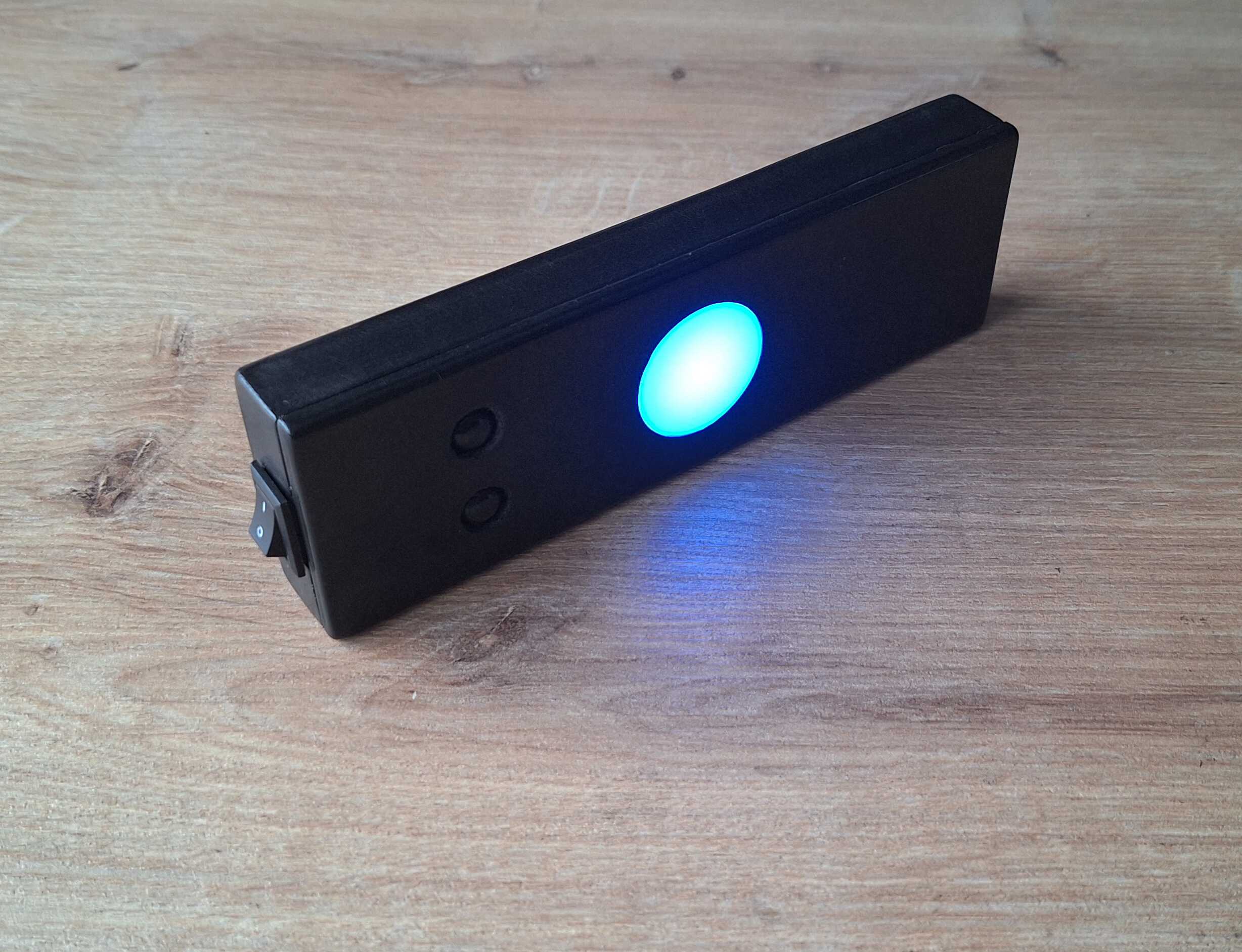
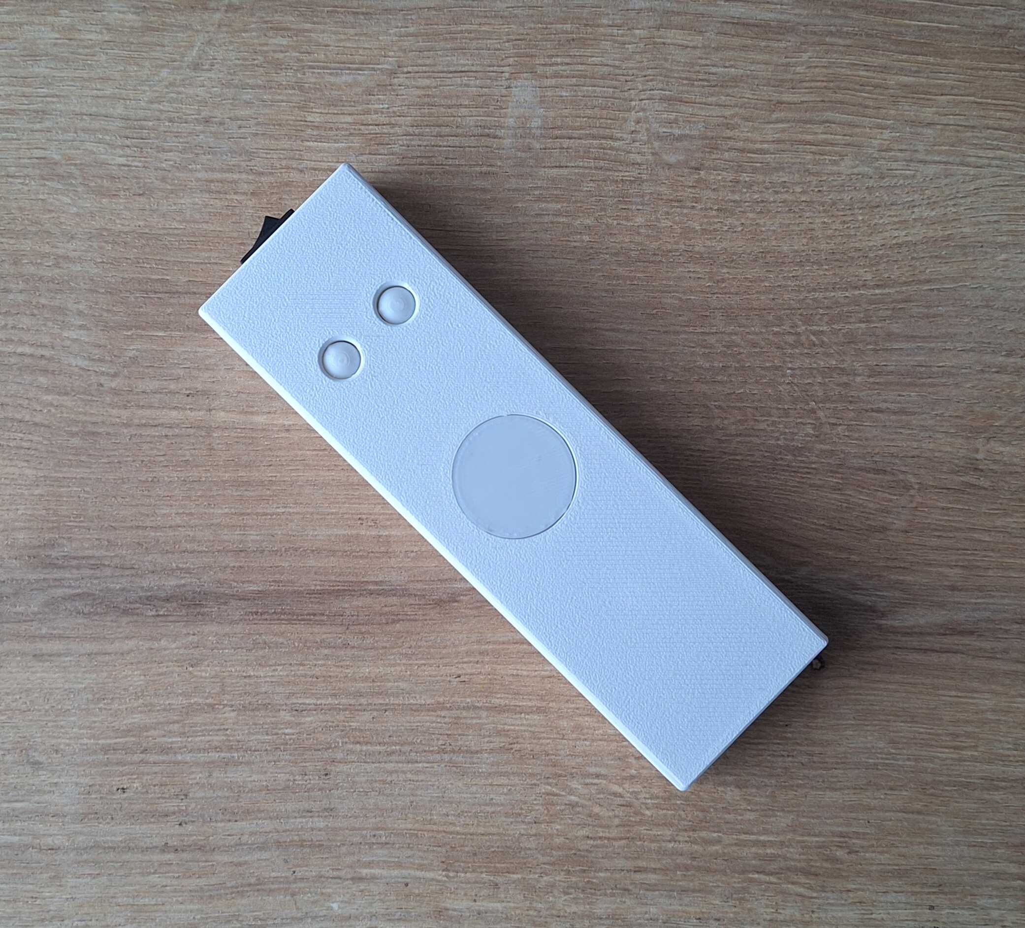
So, this gadget has two buttons - for two such breathing excercises.
Pressing one starts a 5 minute timer, during which the thing will tell
you to breathe in or out (or hold to your breath) at certain interval
by vibrating and lighting up the white dot.
For you, dear reader, I've programmed a demo when you press both
buttons. Turn the audio on for full effect.
It walks!
I found out that if you hold on to something vibrating for 5 minutes
your hand feels funny, so in reality the vibration is a lot more
gentle, you can barely hear it in the video below.
Boop!
What's Inside
I wanted to make this as small as possible, although it still came out
kind of large, everything inside is tiny! Here's the meat and potatoes
with some money for scale.
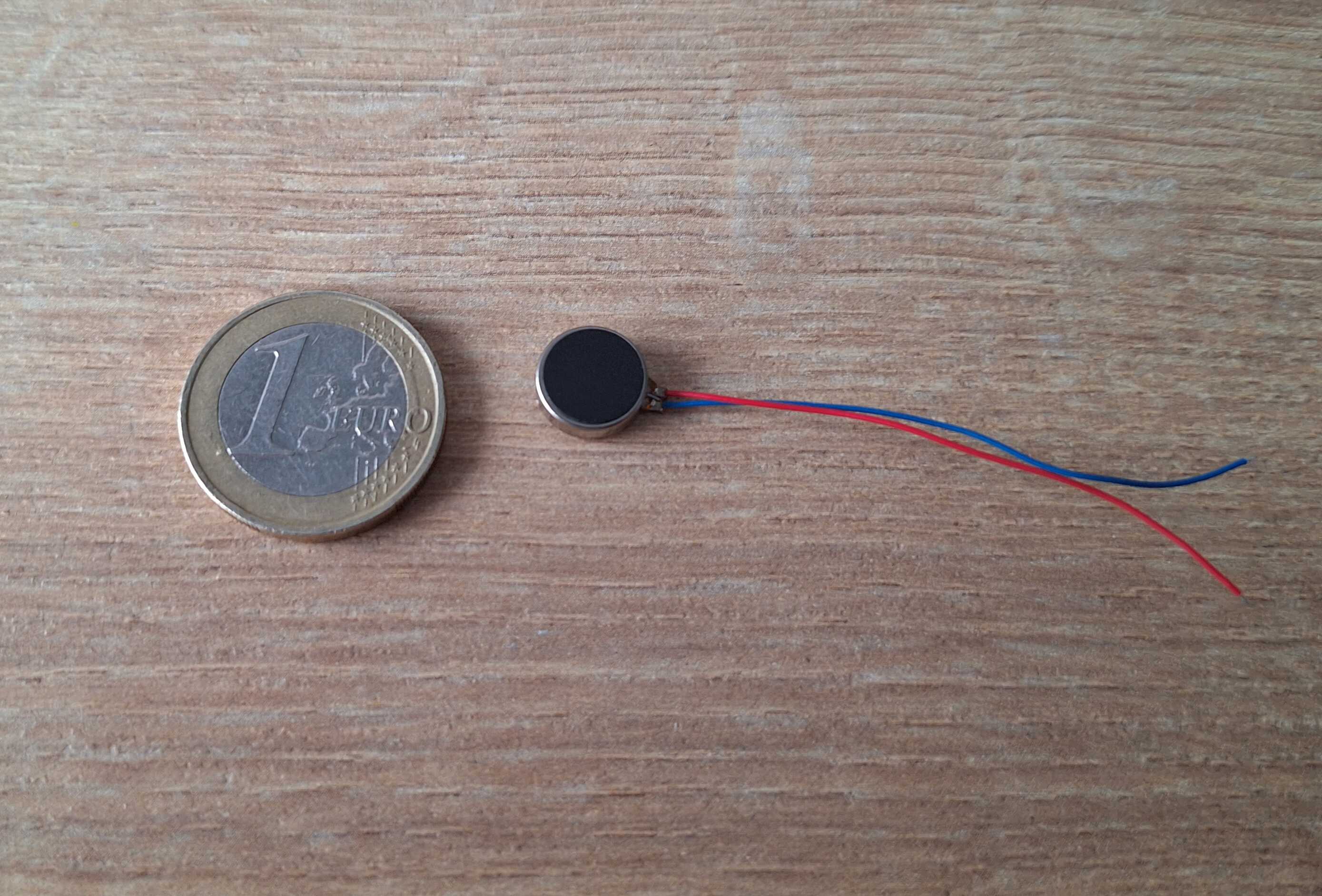
Vibrating motor AKA coin motor
Bulb type LEDs are ok, but this one shines so bright they could have
used it for Batman signal.
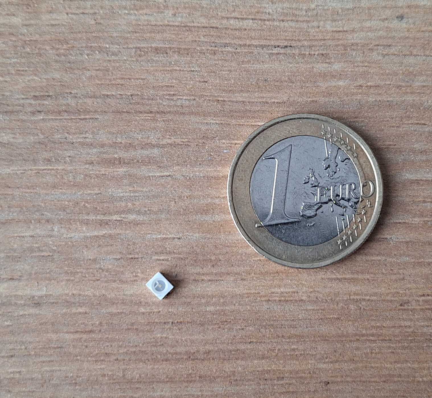
Na na na na na na na na bat man!
Tiny 250 mAh battery, for comparison my phone has capacity of 5000
mAh.
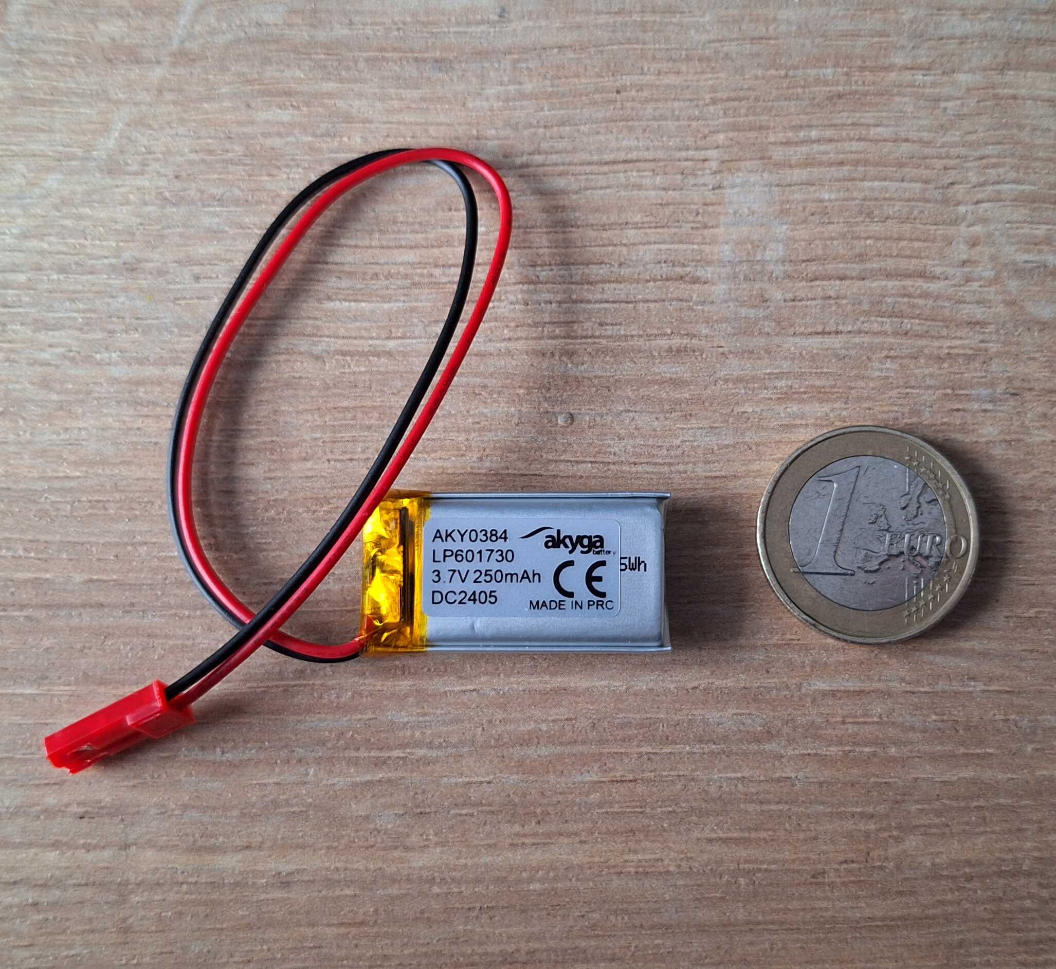
Capacity of, like, three electrons
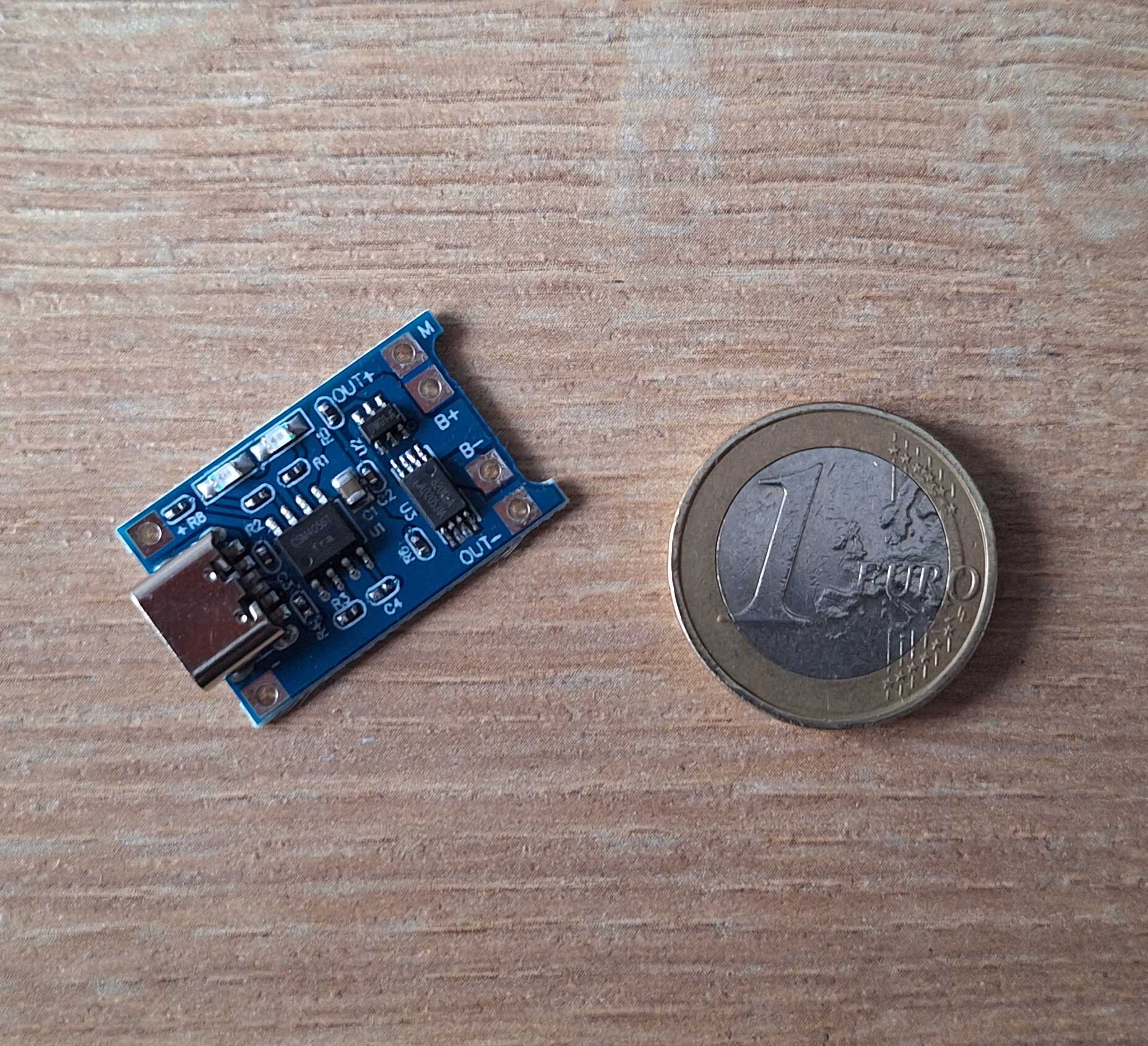
Battery charger - has USB port for charging and protects battery from
overcharging. Also has lights.
The brain of this operation, ATTiny85 microchip, low energy
programmable tiny computer, to toggle motor and LED, and also track
time.
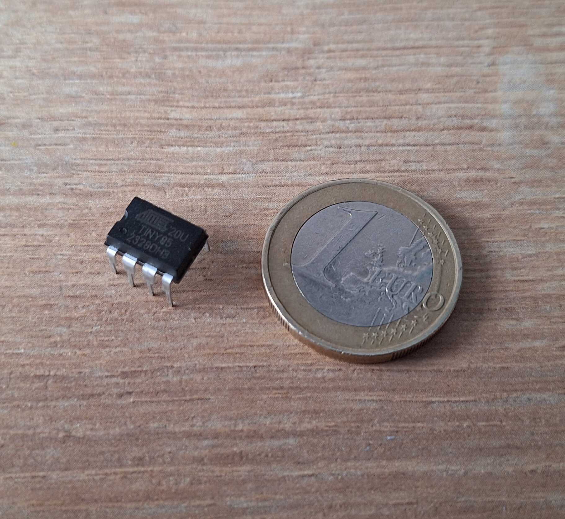
Tinychip *ba dum tss*
Connecting Things
First thing I wanted to try is the vibrating motor, never had one of
those and I've read beforehand that you can't connect it directly to
"the brain" (chip), because it draws higher current than chip can
provide, resulting in "brain damage" (burned chip).
You can connect motor directly to the battery, it works fine, battery
is fine, all is well, but it will just vibrate endlessly, we need a way
to turn it on and off.
It would be great if we could connect a switch between battery and
motor, which would turn it on and off, same way you have switches on
the wall at home which turn the lights on or off.
It would be even better if "the brain" could control that switch, like
tiny hand going *click*.
And to do the above, we can use a transistor which can act like a
switch. It has three legs, one goes to battery, another to motor and
the third one acts like a button on the light switch that you push at
home, but instead of tiny hand going *click*, tiny brain produces
voltage which flips the switch.
This setup works, but we need to take care of one more thing I've read
about while trying to figure this out - turning the motor off can
create a voltage spike, which in turn might damage the transistor. For
this problem I've got a diode, connecting it to both leads of motor
should absorb motor fuck ups.
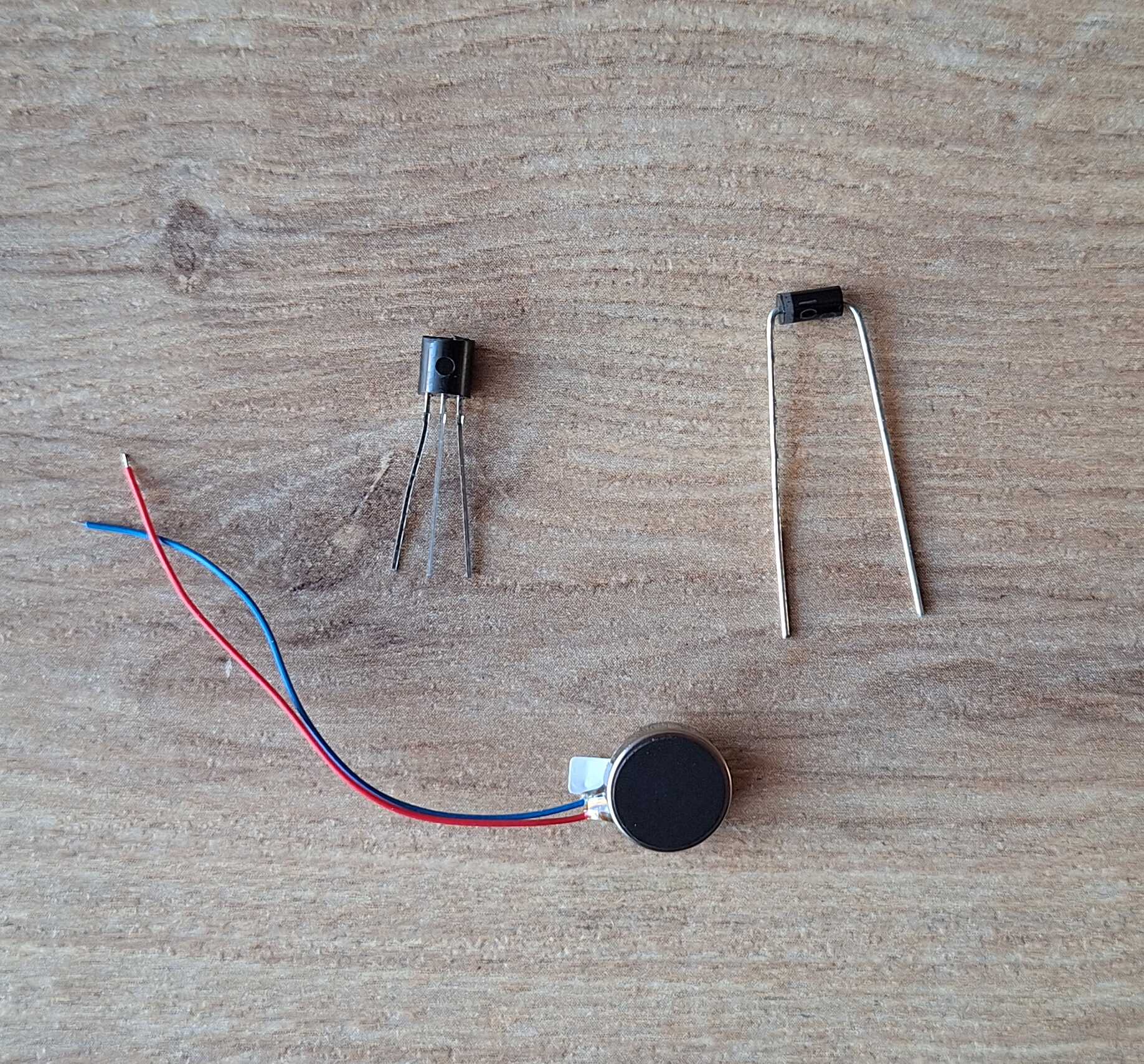
The three amigos - transistor, motor and diode
To test this quickly, instead of using the chip to toggle the
transistor, I hooked it up to a button and let it rip.
Look at him go!
Next thing to try is the microchip, we need to program it, so it would
turn on the motor instead of me having to hold down a button. But how
do you communicate with something that has no USB sockets, only 8 metal
legs? You need something that has USB socket and deals with 8 legs of a
chip, that something is called USBasp programmer.
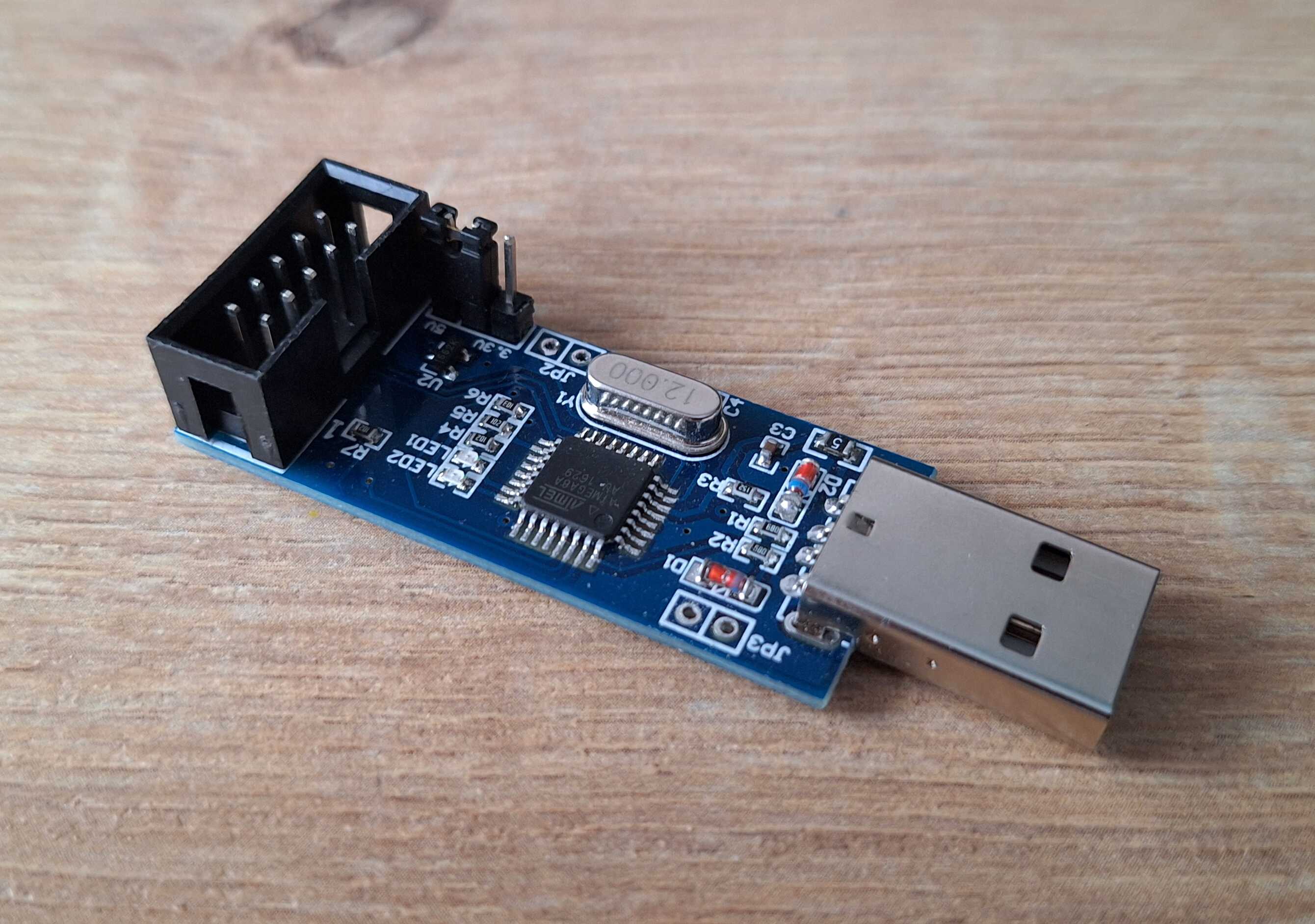
As you can see it also has some legs, we connect those to our little
guy and now we can transfer some code to it.
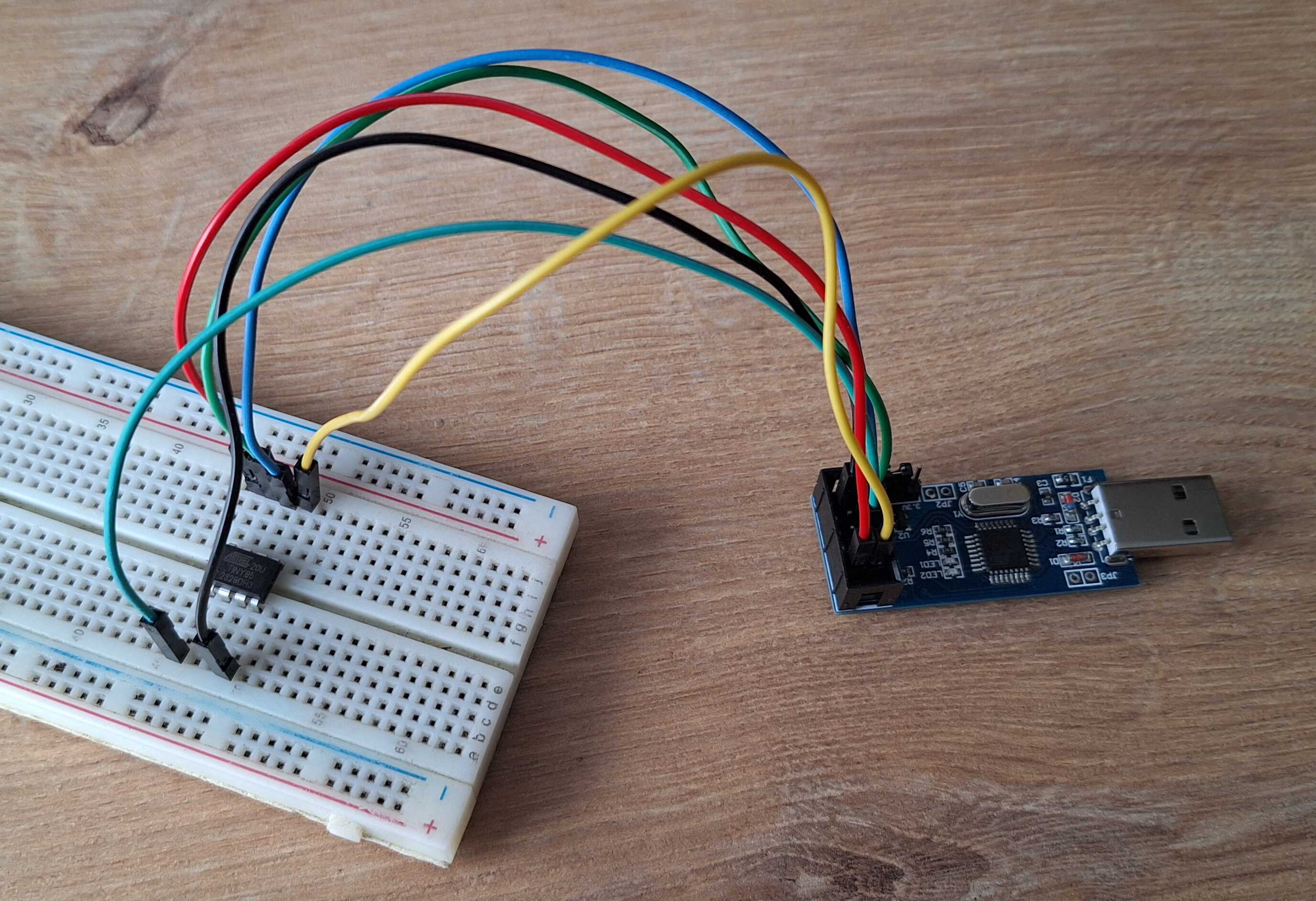
Connected with the help of a breadboard
Putting it all together we get this monstrosity.
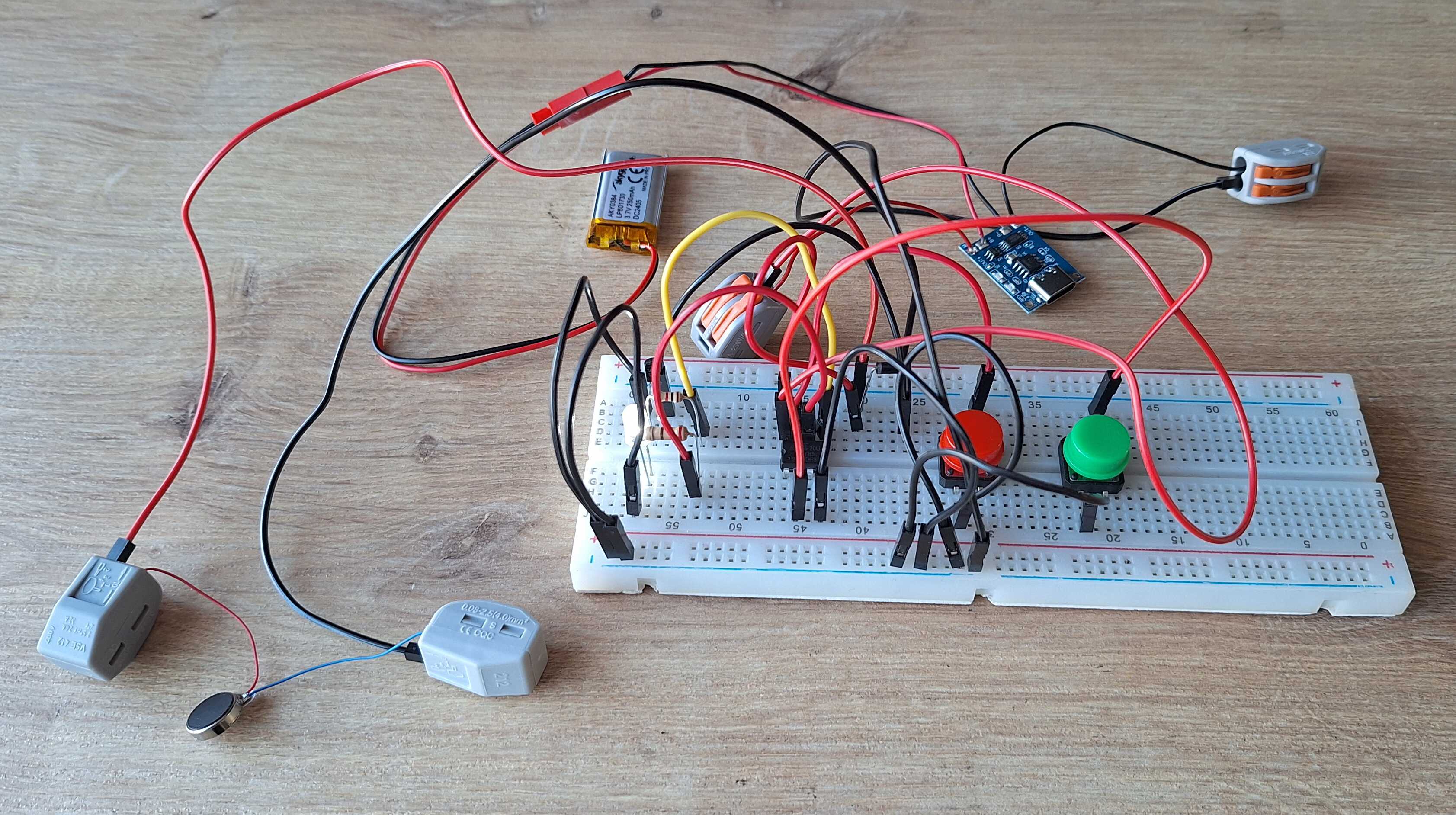
Good lord
Looks awful, but it works, so we have that going for us. Now onto
making this look a bit better.
Putting Things In a Box
To put the above into enclosure and not have the enclosure be the size
of a brick, we need to get rid of some wires and put everything on a
copper clad board.
I'll make the PCB (printed circuit board) myself, like I did when
I made a digital clock, but we're a long way off from drawing on the board by hand, no, we're
high-tech now.
I've got a laser printer and some transparent paper, so I can print
traces.
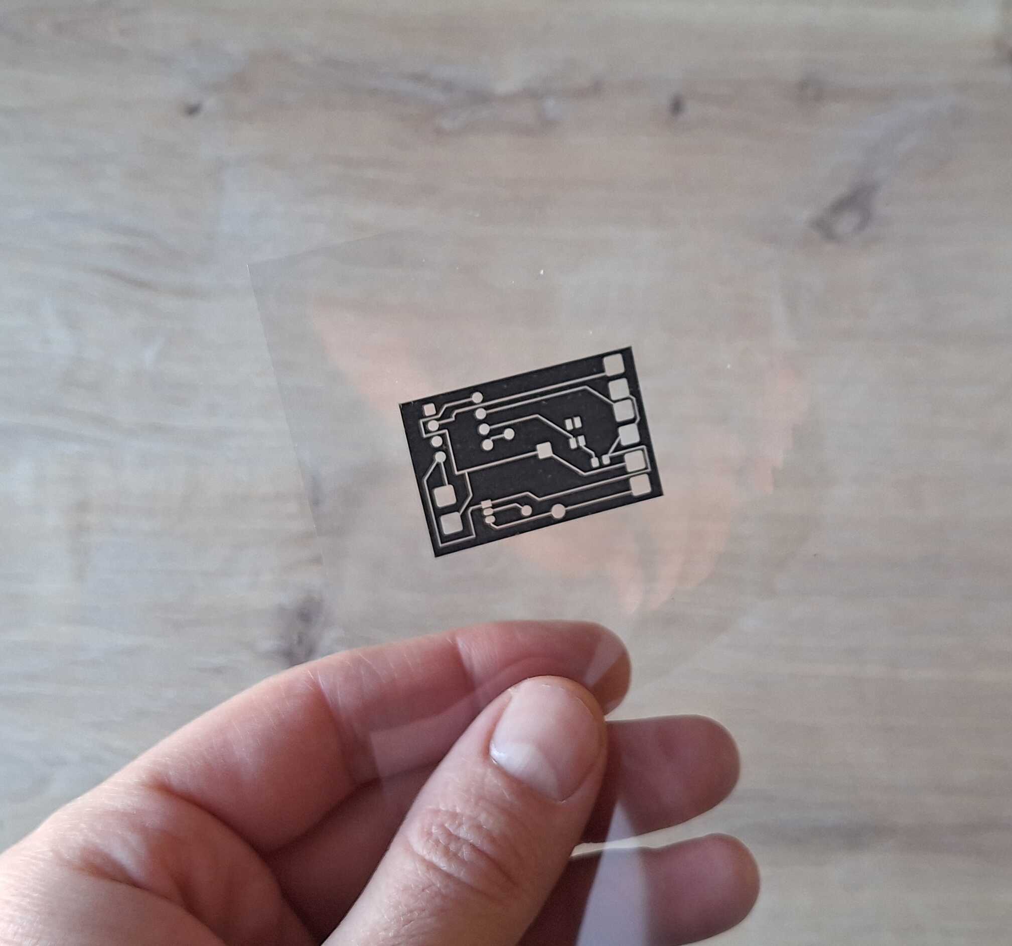
So high-tech
I made the image above using KiCad, here's how it looks like.
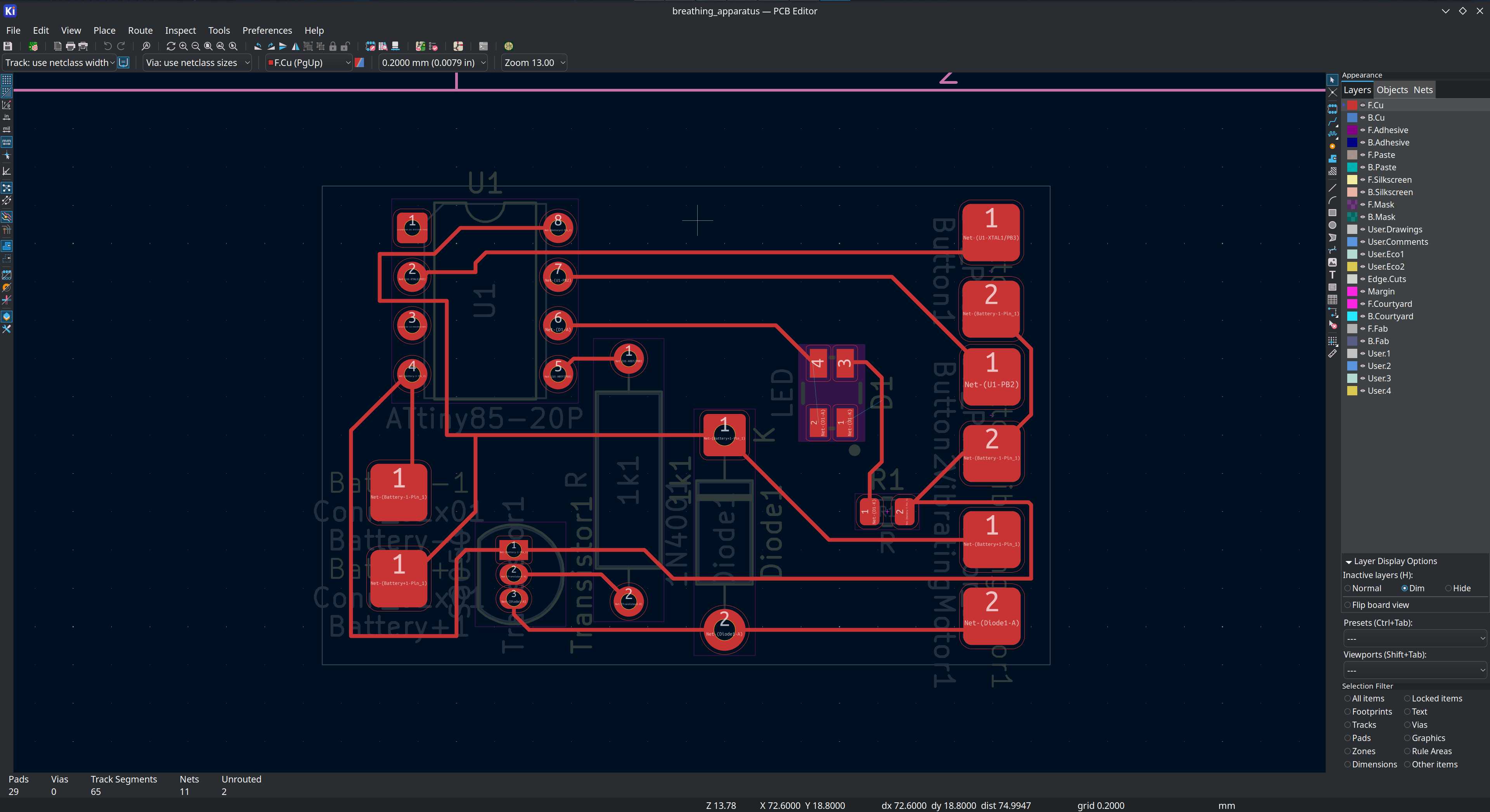
KiCad
Then I got some photoresist paper that I tack on the copper clad board.
The purpose of it is to stick to the board where the traces are
supposed to be, allowing me to skip drawing those by hand with a black
marker.
As it doesn't stick very well, I run it through a laminator machine,
but pressing down with a hot iron should also work.
Piece of paper so the thing would grab it
We need to put the transparent paper with traces on top and shine some
light on it. You could use a lamp or just leave it under the sun, the
results will vary though - light might leak under the traces if you
keep it under a light for too long, you have to time it differently for
each light source, so for more consistent results I used ultraviolet
LEDs.
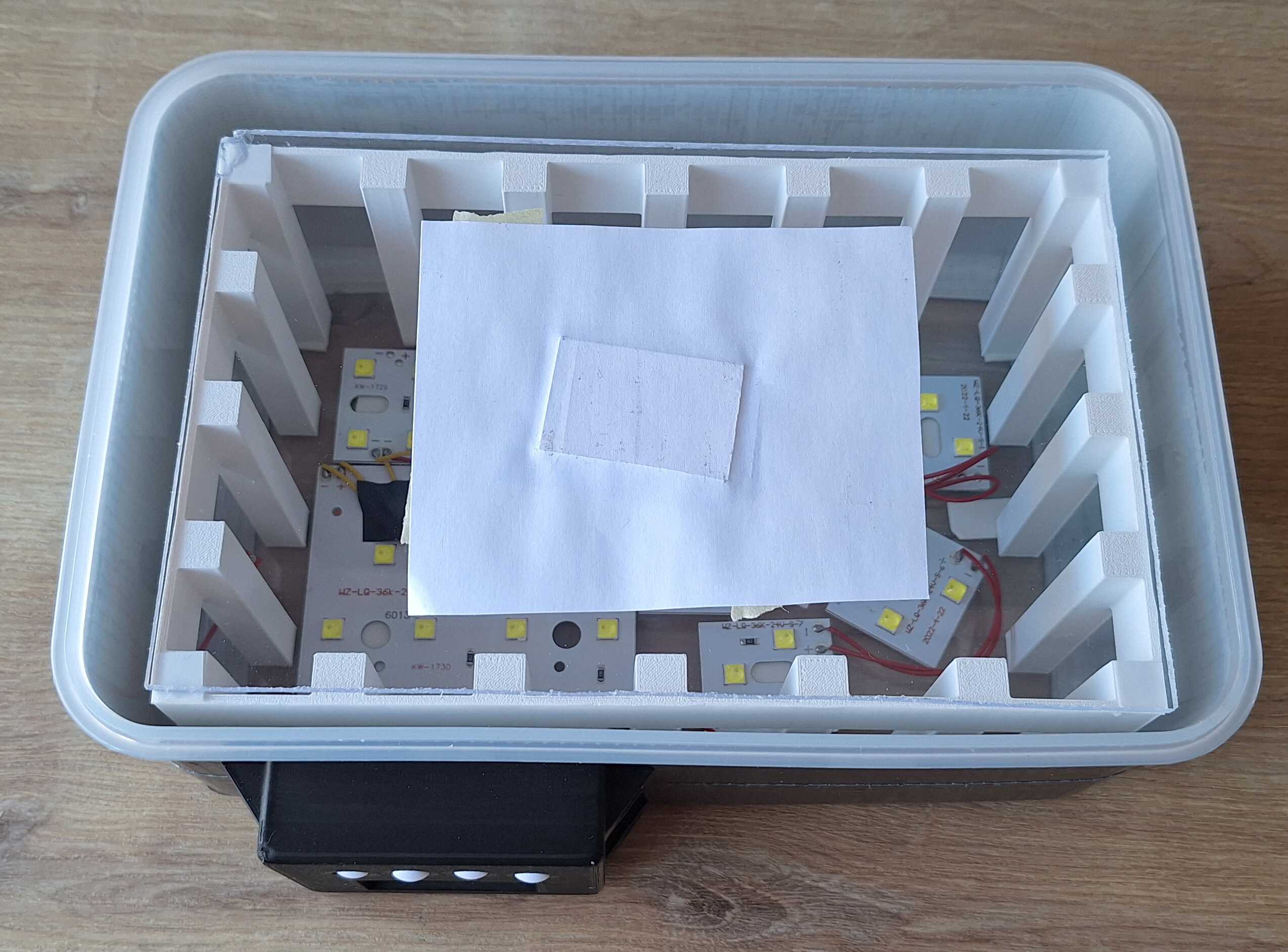
Unfortunately ultraviolet LEDs are expensive, so I found this thing
that is used to dry nails and is cheap.
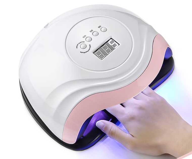
They don't seem to have anything on the nails to dry though
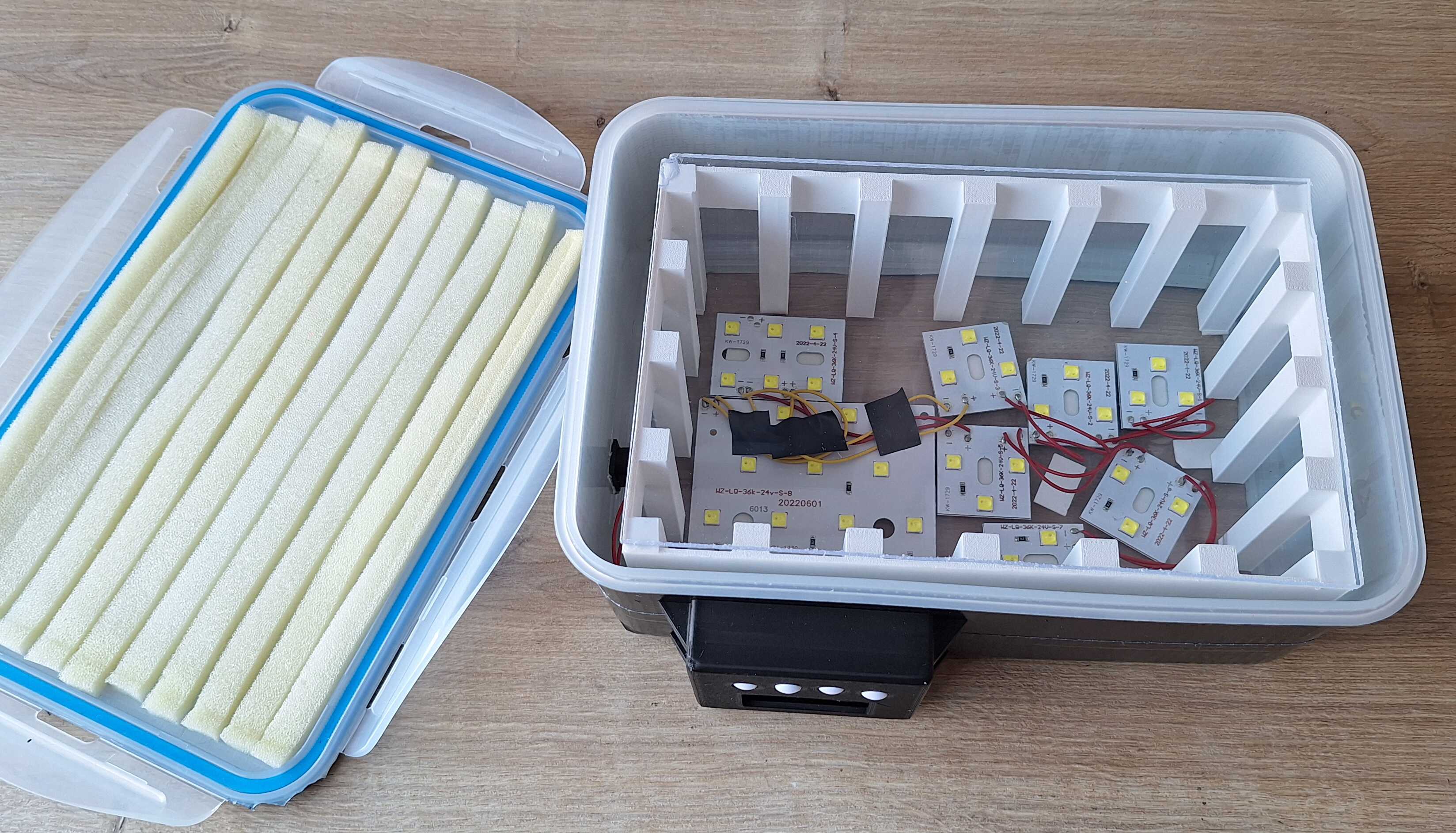
It has some ultraviolet LEDs and a timer mechanism with a display. I
took it apart and stuffed everything into a plastic lunchbox.
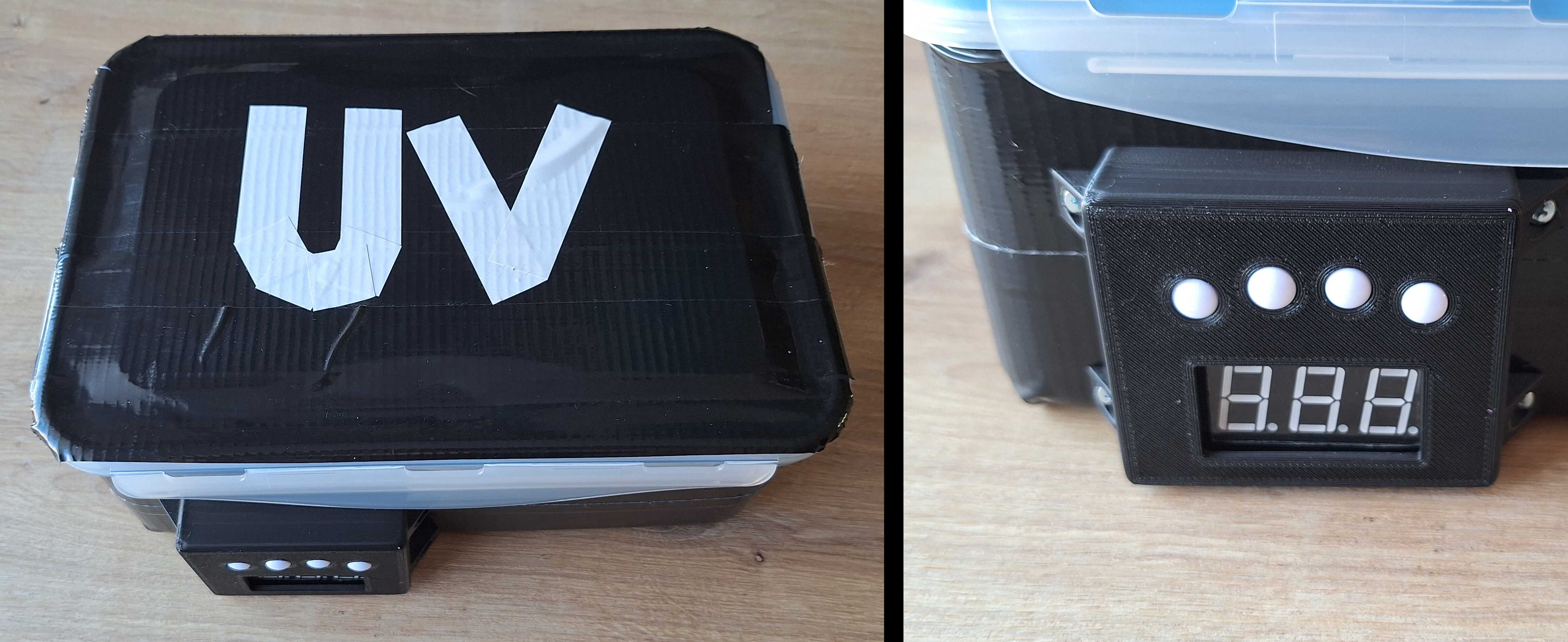
Just need to remember what the buttons do
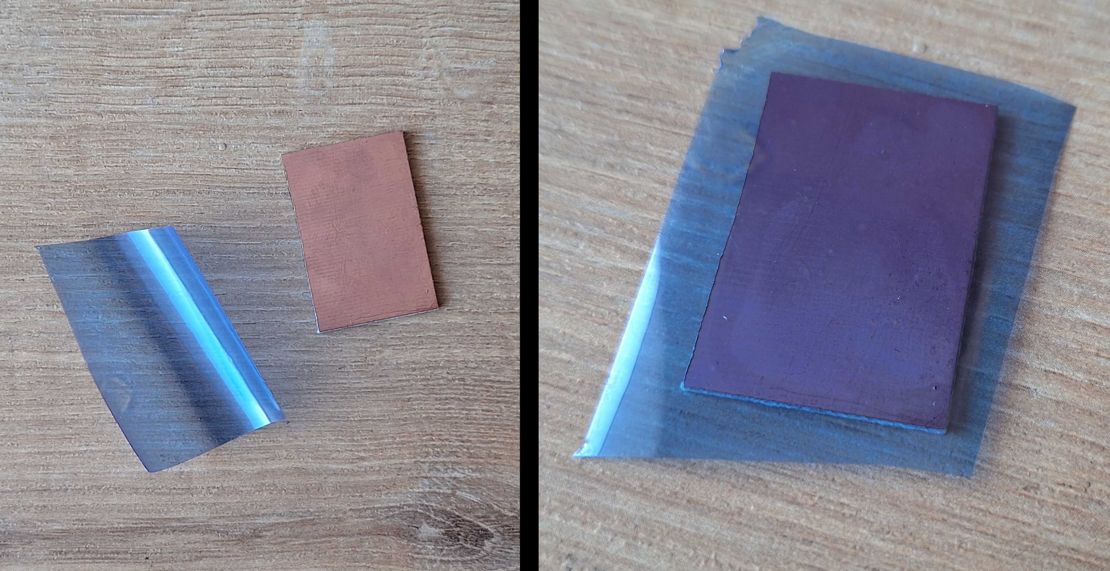
There's an acrylic piece of glass on top of those white stilts, that's
where we put printed traces and coppper board on top of them, along
with the paper that got glued the photo resist paper.
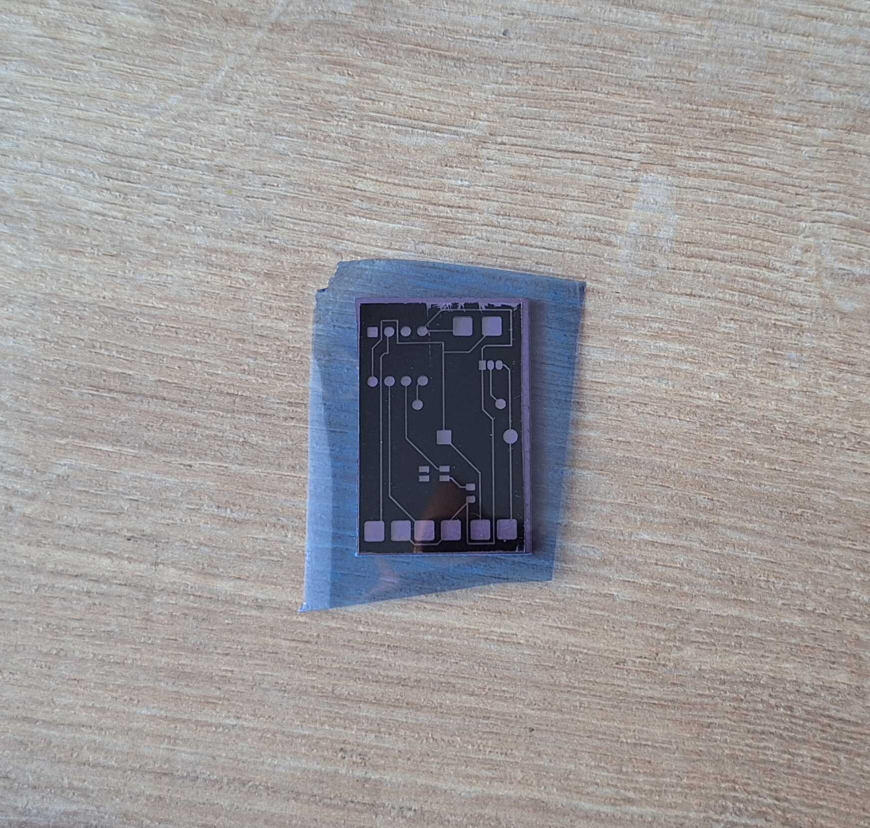
Photo before laminator, from bottom: copper board, photo resist paper,
traces printed on transparent paper
Off you go!
All it needs is 5 seconds.
Atomic lunchbox
Where nothing was printed on transparent paper, the light hardened
photo resist paper and now it stuck even more to the copper board. The
rest is easily cleaned off - mix a cup of water with a teaspoon of
drain cleaner (don't use a teaspoon you eat with), throw the board in
there and wait for a bit.
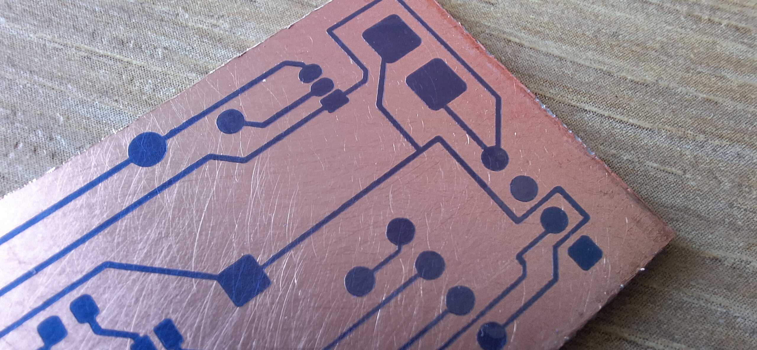
Next I dumped it into ferric chloride to etch visible copper away.
Almost perfect
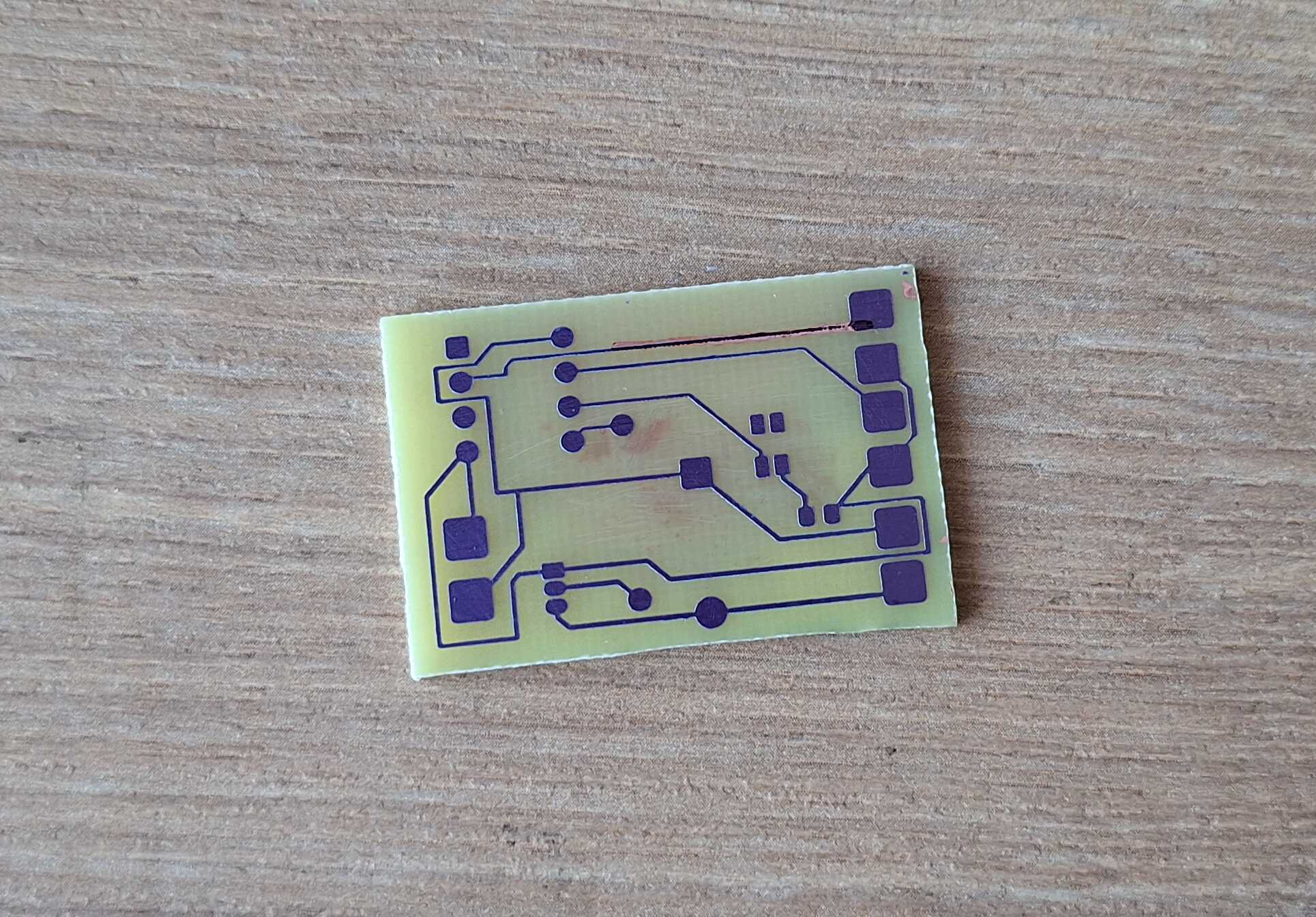
Now all that's left is photo resist paper and copper underneath it -
we'll get to it by rubbing acetone on the board.
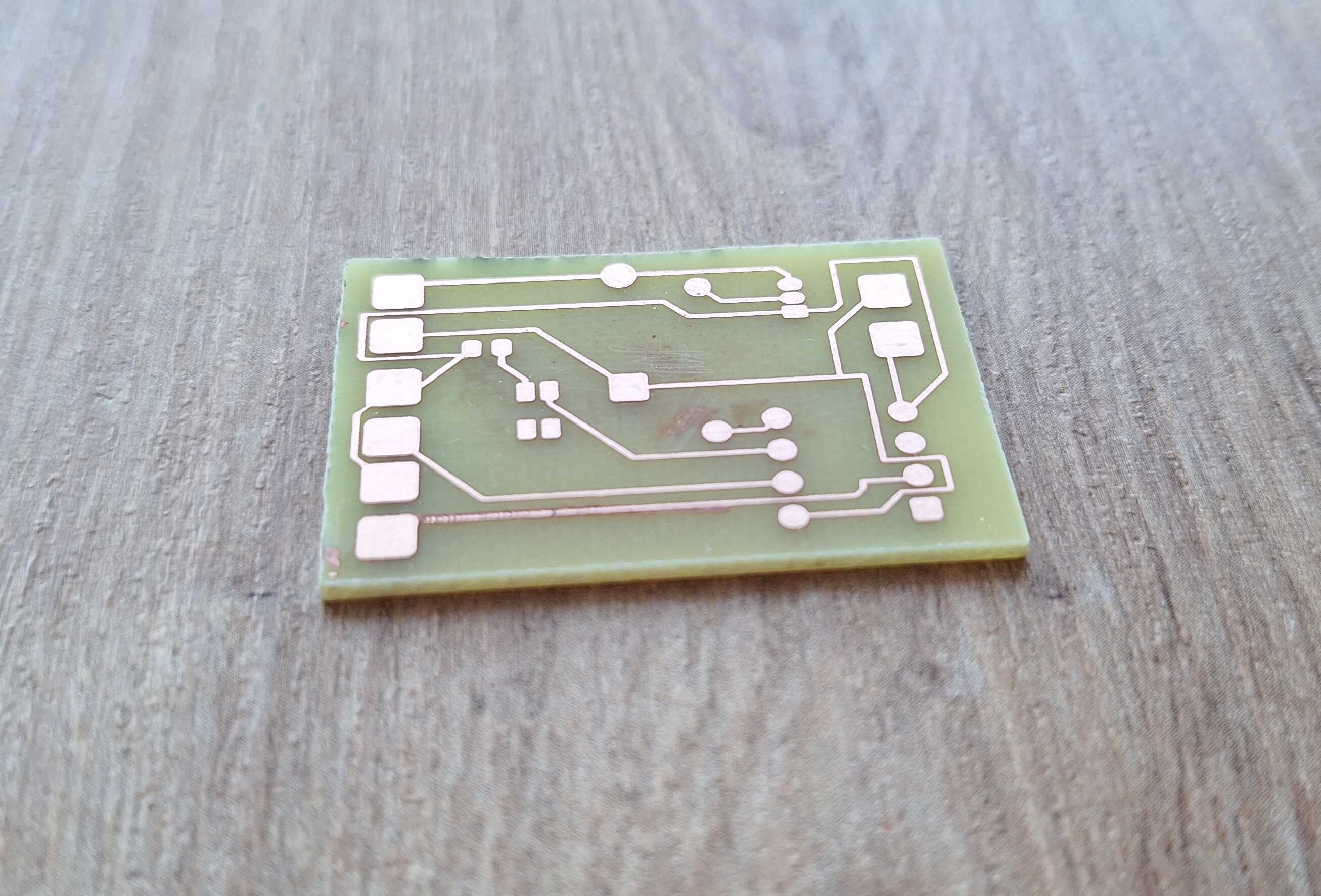
Like bus lanes for electron citizens
After drilling some holes where appropriate, I soldered everything into
place.
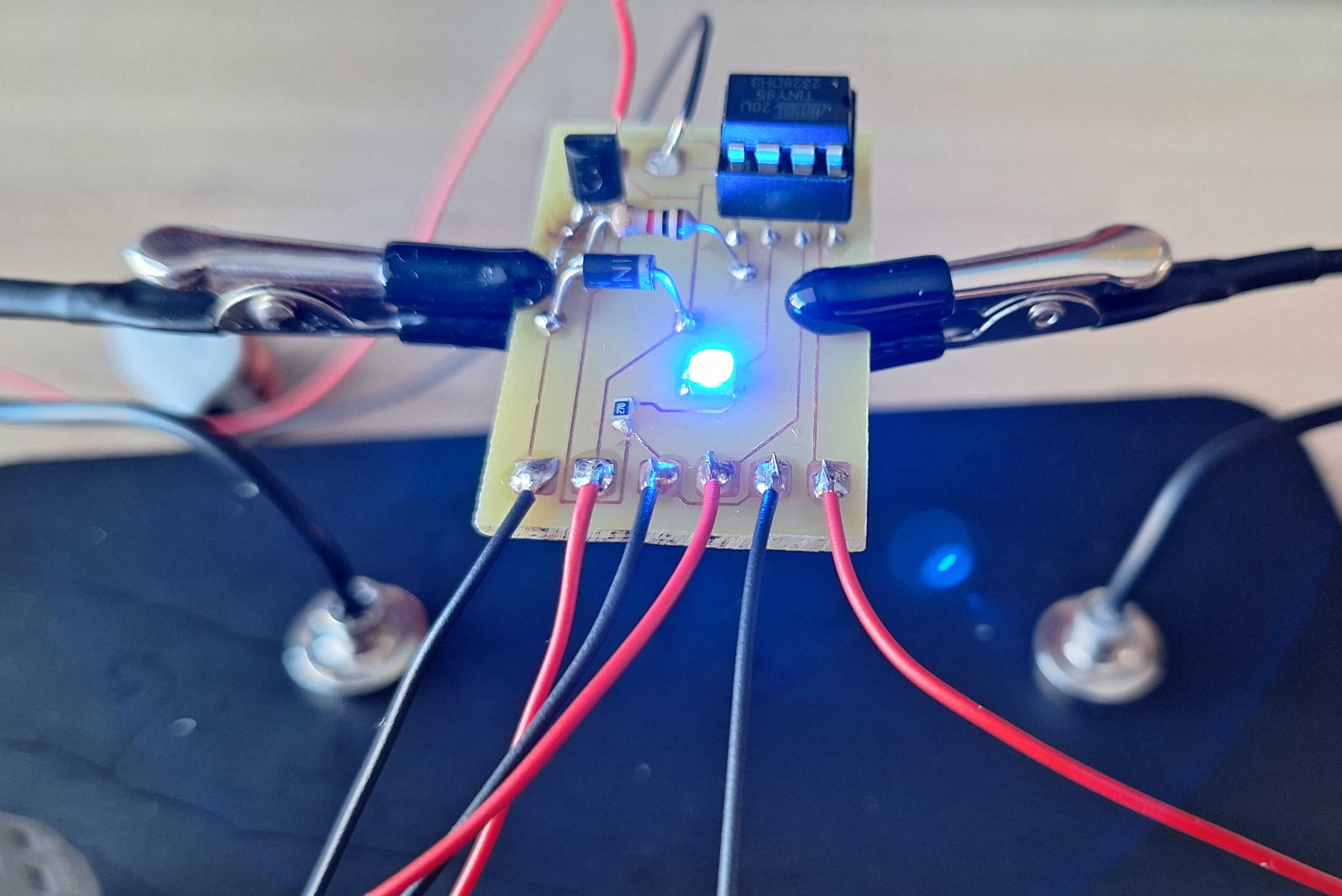
Terrific
I created the enclosure model using FreeCAD and then 3D printed it.
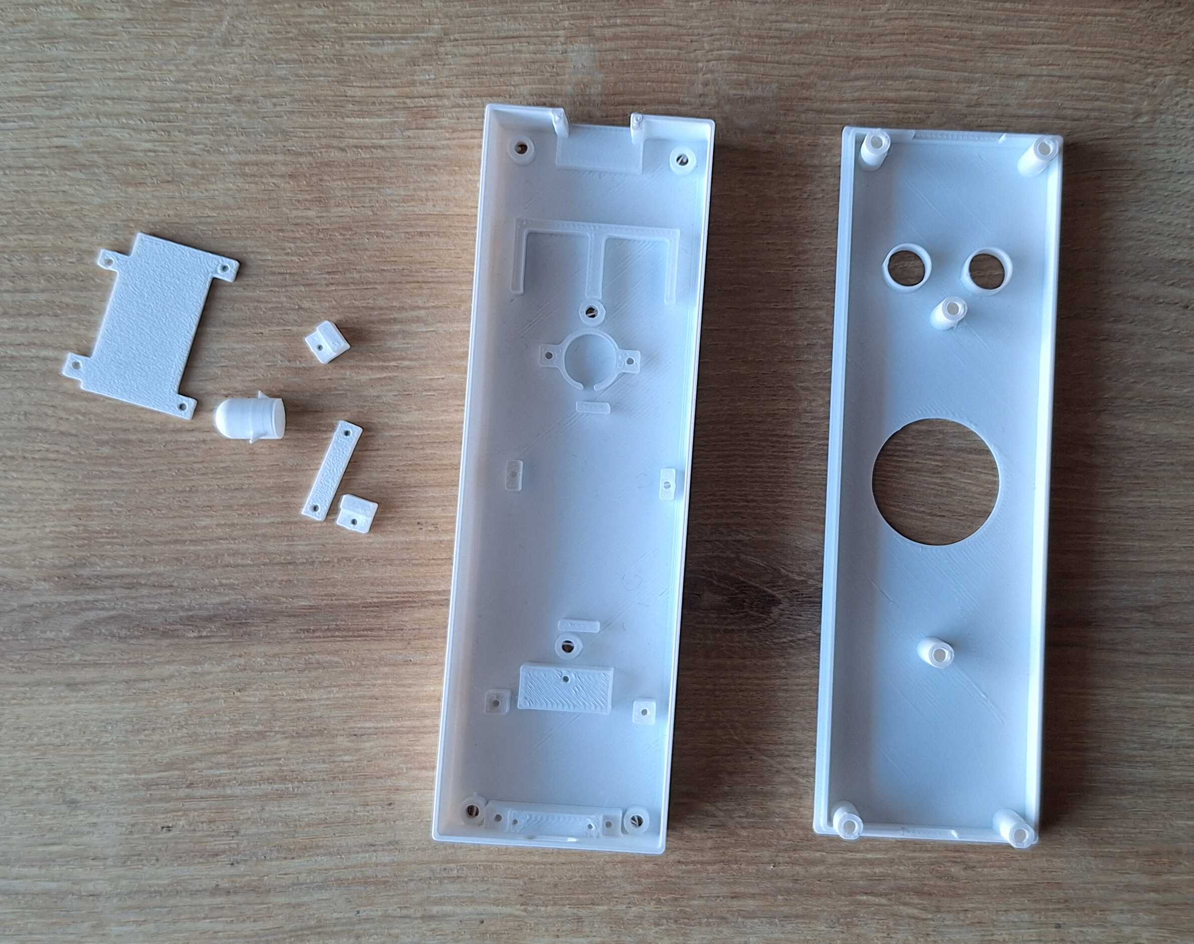
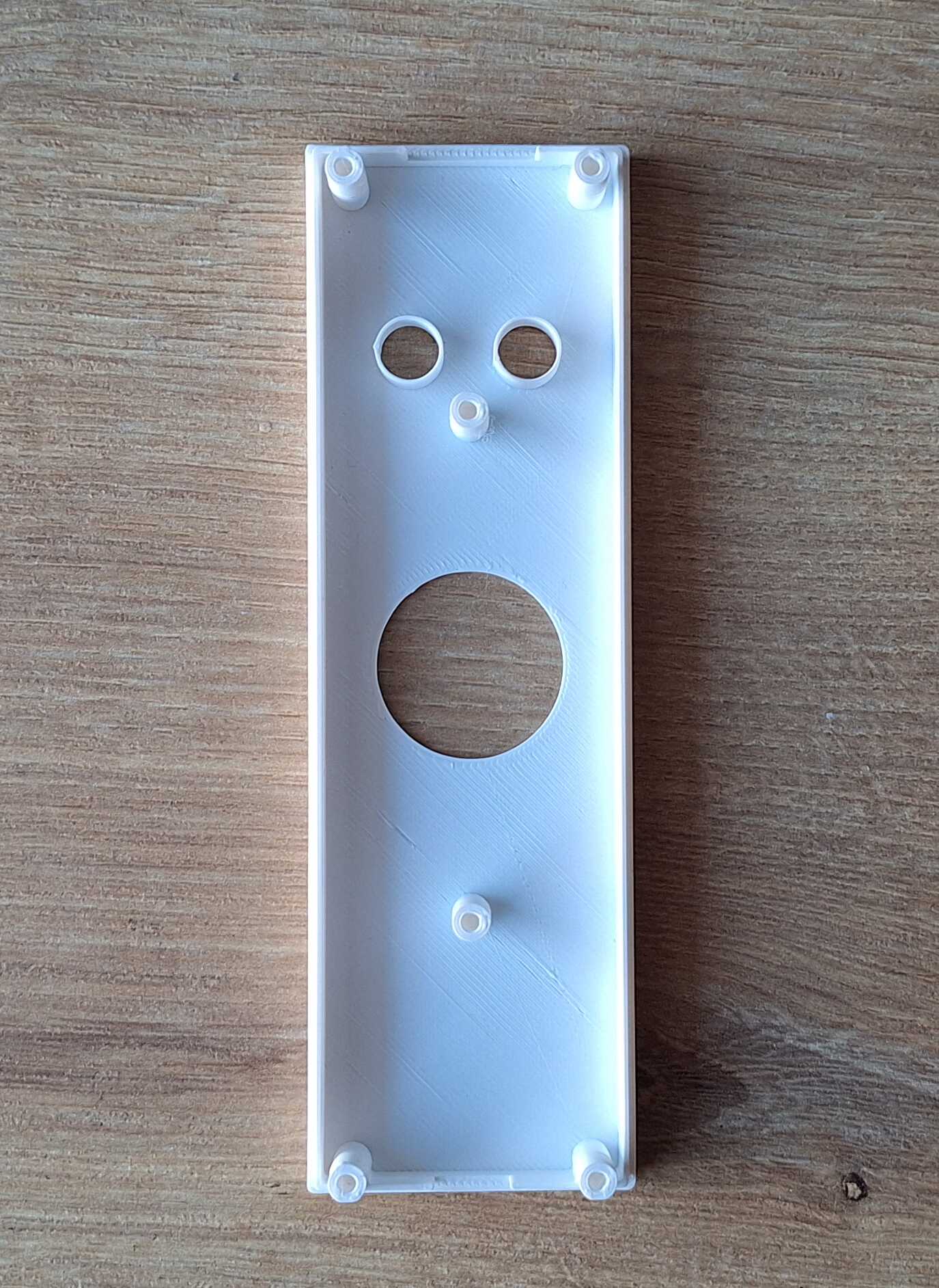
He looks surprised
Then I started adding components and cutting down wires to length.
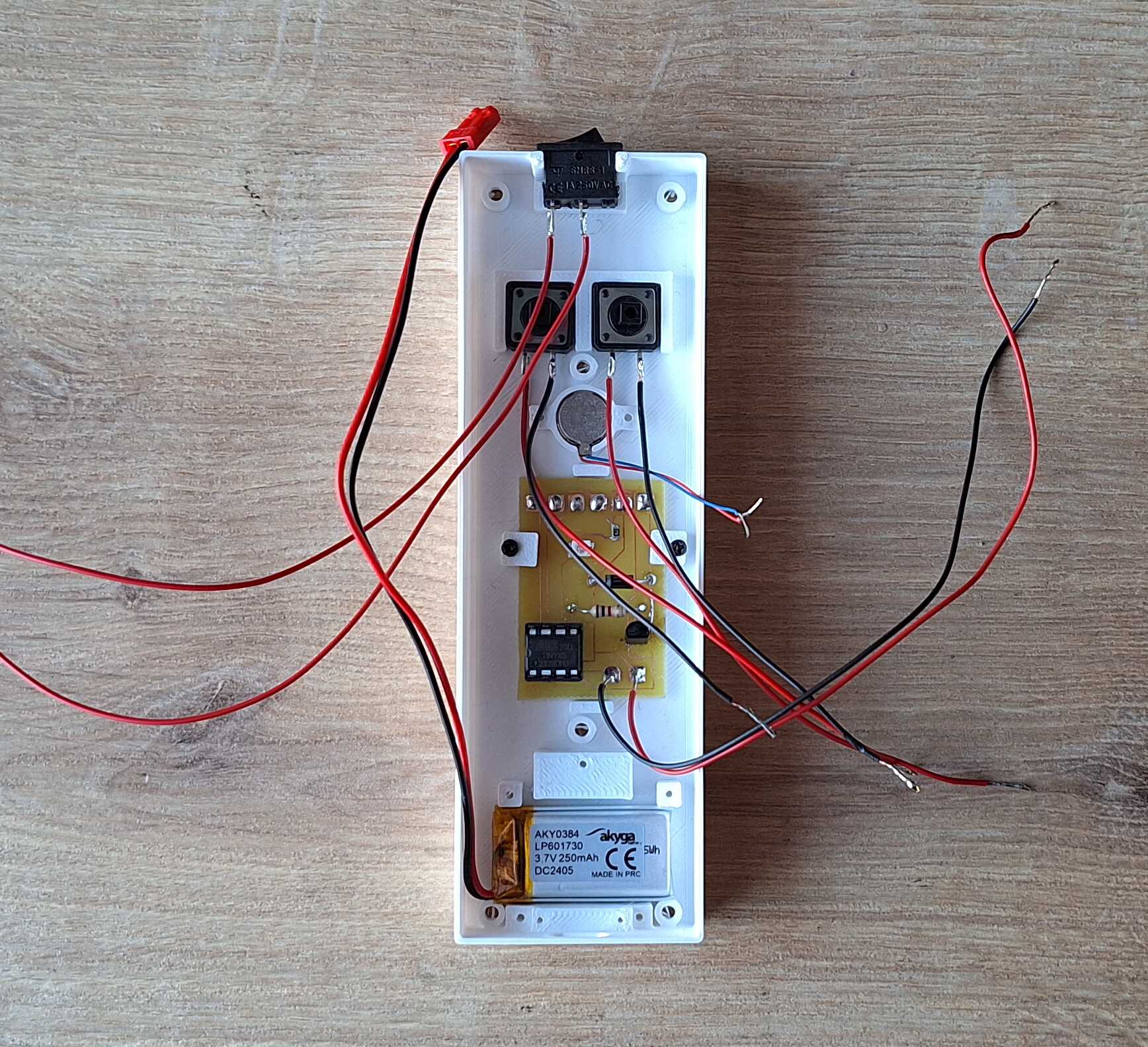
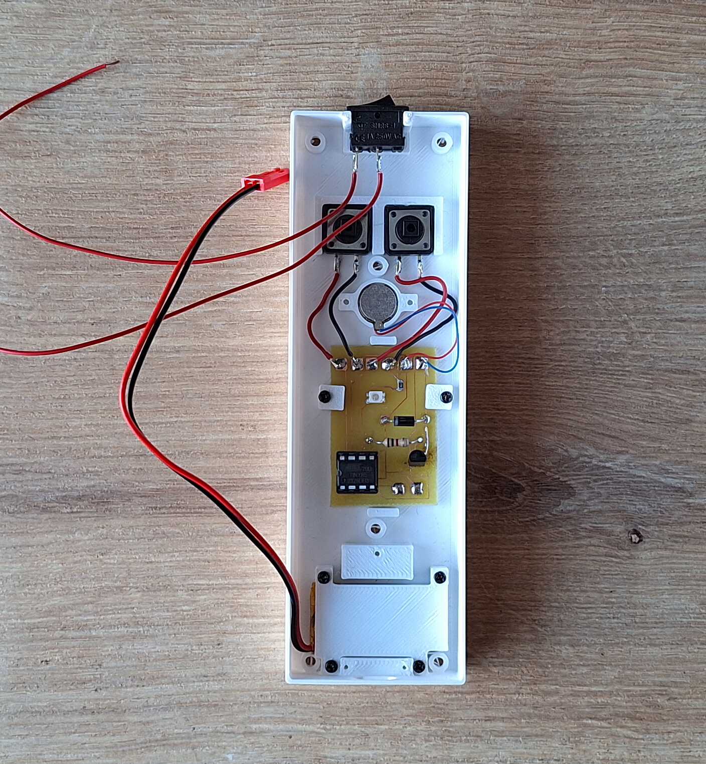
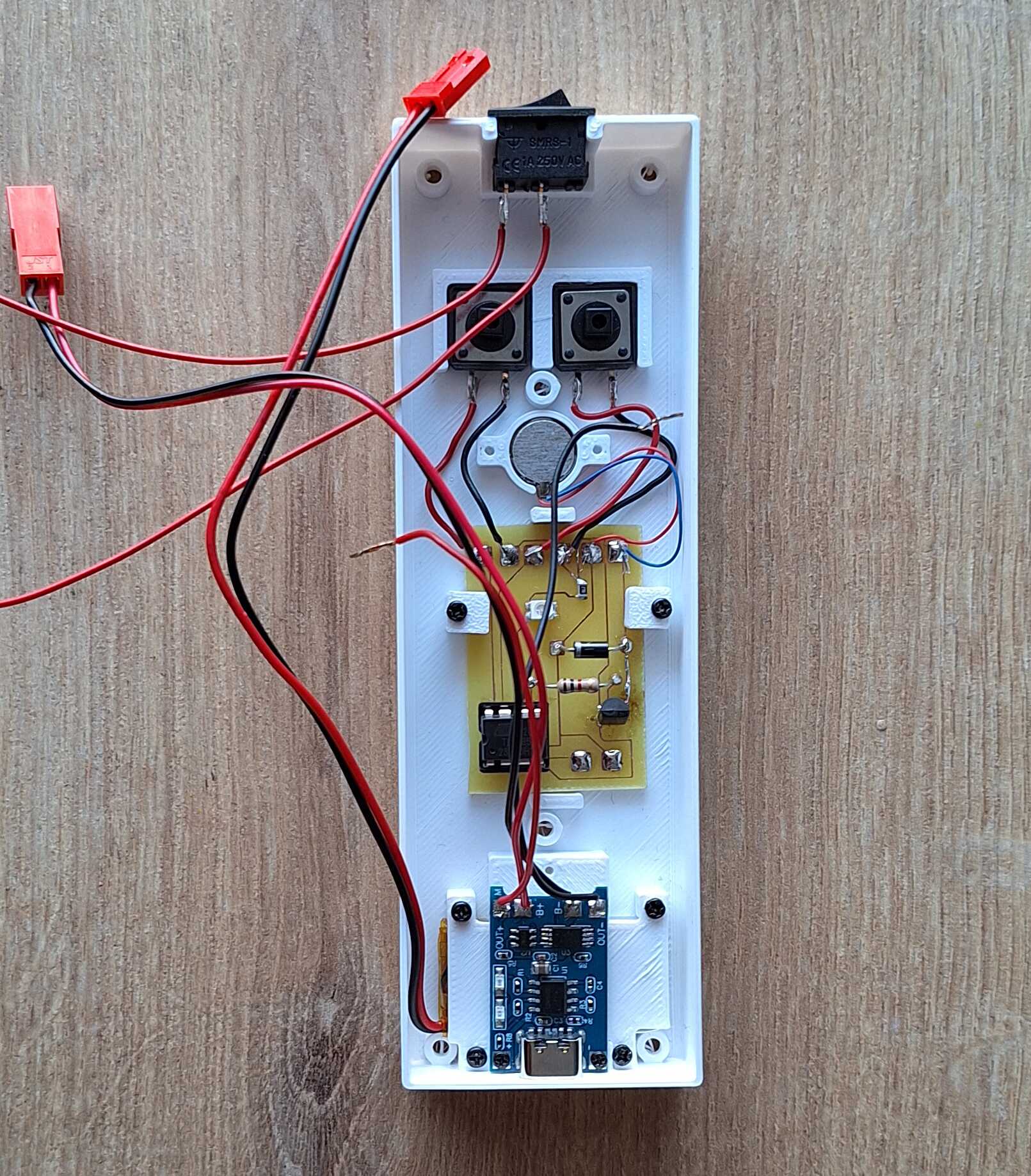
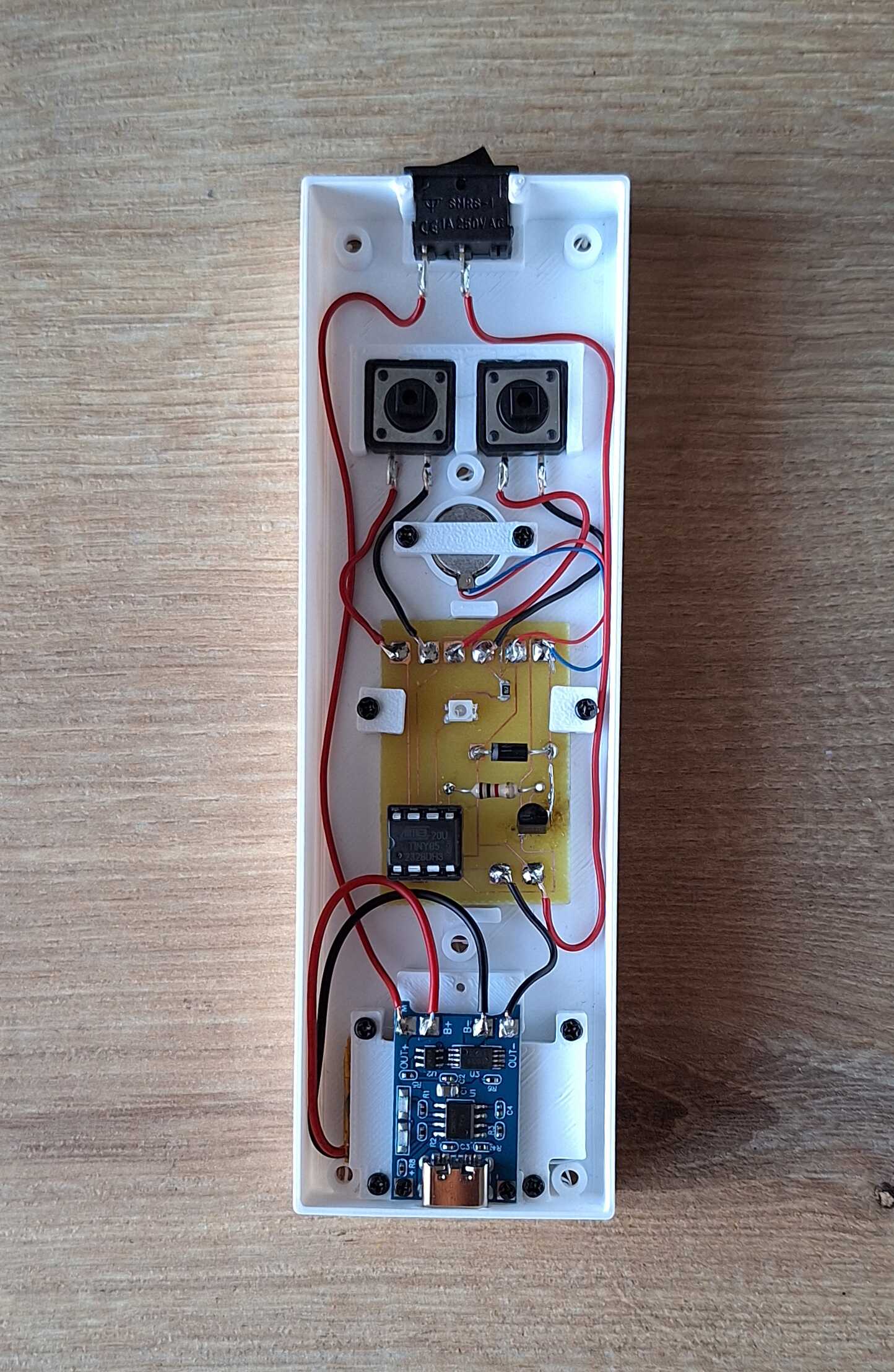
:o
Code
Here's the code that powers this thing. To get some utility functions
and make my life easier, I used Arduino lib.
#include <Arduino.h>

int motorPin = 0;
int ledPin = 1;
int buttonEx1 = 2;
int buttonEx2 = 3;

#define VIBRATION_DURATION 20
#define VIBRATION_LONG_DURATION 40
#define LED_CHANGE_STEP 1

const int ledPulseDuration = (255 * LED_CHANGE_STEP) * 2;

int excercise1[] = {4, 7, 8};
int excercise2[] = {6};

void ledOn() {
  for (int i = 0; i <= 255; i++) {
    analogWrite(ledPin, i);
    delay(LED_CHANGE_STEP);
  }
}

void ledOff() {
  for (int i = 255; i >= 0; i--) {
    analogWrite(ledPin, i);
    delay(LED_CHANGE_STEP);
  }
}

void vibrateWithLedPulse() {
  digitalWrite(motorPin, HIGH);

  for (int i = 0; i <= 255; i++) {
    analogWrite(ledPin, i);
    delay(LED_CHANGE_STEP);

    if (i >= VIBRATION_DURATION) {
      digitalWrite(motorPin, LOW);
    }
  }

  for (int i = 255; i >= 0; i--) {
    analogWrite(ledPin, i);
    delay(LED_CHANGE_STEP);
  }
}

void vibrateAndSwitchOffLed() {
  digitalWrite(motorPin, HIGH);

  for (int i = 255; i >= 0; i--) {
    analogWrite(ledPin, i);
    delay(LED_CHANGE_STEP);

    if (i <= 255 - VIBRATION_DURATION) {
      digitalWrite(motorPin, LOW);
    }
  }
}

void vibrate() {
  for (int i = 0; i < 2; i++) {
    digitalWrite(motorPin, HIGH);
    delay(VIBRATION_LONG_DURATION);
    digitalWrite(motorPin, LOW);
    delay(VIBRATION_LONG_DURATION);
  }
}

void runExcercise(int ex[], int size) {
  unsigned long startAt = millis();
  unsigned long interval = 5 * 60 * 1000UL;

  bool firstRun = true;

  while (true) {
    for (int i = 0; i < size; i++) {
      if (firstRun) {
        firstRun = false;
        vibrateAndSwitchOffLed();
      } else {
        vibrateWithLedPulse();
      }
      delay((ex[i] * 1000) - ledPulseDuration);
    }

    unsigned long duration = millis() - startAt;
    if (duration >= interval) {
      break;
    }
  }

  vibrate();
  ledOn();
}

void demo() {
  while (true) {
    digitalWrite(motorPin, HIGH);

    for (int i = 0; i <= 255; i++) {
      analogWrite(ledPin, i);
      delay(LED_CHANGE_STEP);
    }

    for (int i = 255; i >= 0; i--) {
      analogWrite(ledPin, i);
      delay(LED_CHANGE_STEP);
    }

    digitalWrite(motorPin, LOW);

    delay(1000);
  }
}

void setup() {
  pinMode(motorPin, OUTPUT);
  digitalWrite(motorPin, LOW);

  pinMode(ledPin, OUTPUT);

  pinMode(buttonEx1, INPUT_PULLUP);
  pinMode(buttonEx2, INPUT_PULLUP);

  vibrate();
  ledOn();
}

void loop() {
  if (digitalRead(buttonEx1) == LOW) {
    delay(100);
    if (digitalRead(buttonEx2) == LOW) {
      demo();
      return;
    }
  }

  if (digitalRead(buttonEx1) == LOW) {
    runExcercise(excercise1, sizeof(excercise1) / sizeof(excercise1[0]));
  }

  if (digitalRead(buttonEx2) == LOW) {
    runExcercise(excercise2, sizeof(excercise2) / sizeof(excercise2[0]));
  }
}
Thanks for reading, let me know if you'd like a surprised breathing
apparatus of your own - contacts at the bottom of the page.